Puya PY32F003 based battery charger
Background
I've been trying for a while now to design a good next-generation battery charging core technology that I would be able to widely apply to a new range of products. I've made several starts with some progress, but there's always been something that held me back from finishing. I'm not always entirely sure why I don't finish, sometimes I can put my finger on a reason and sometimes it's much more subtle and something just doesn't feel right about the design.
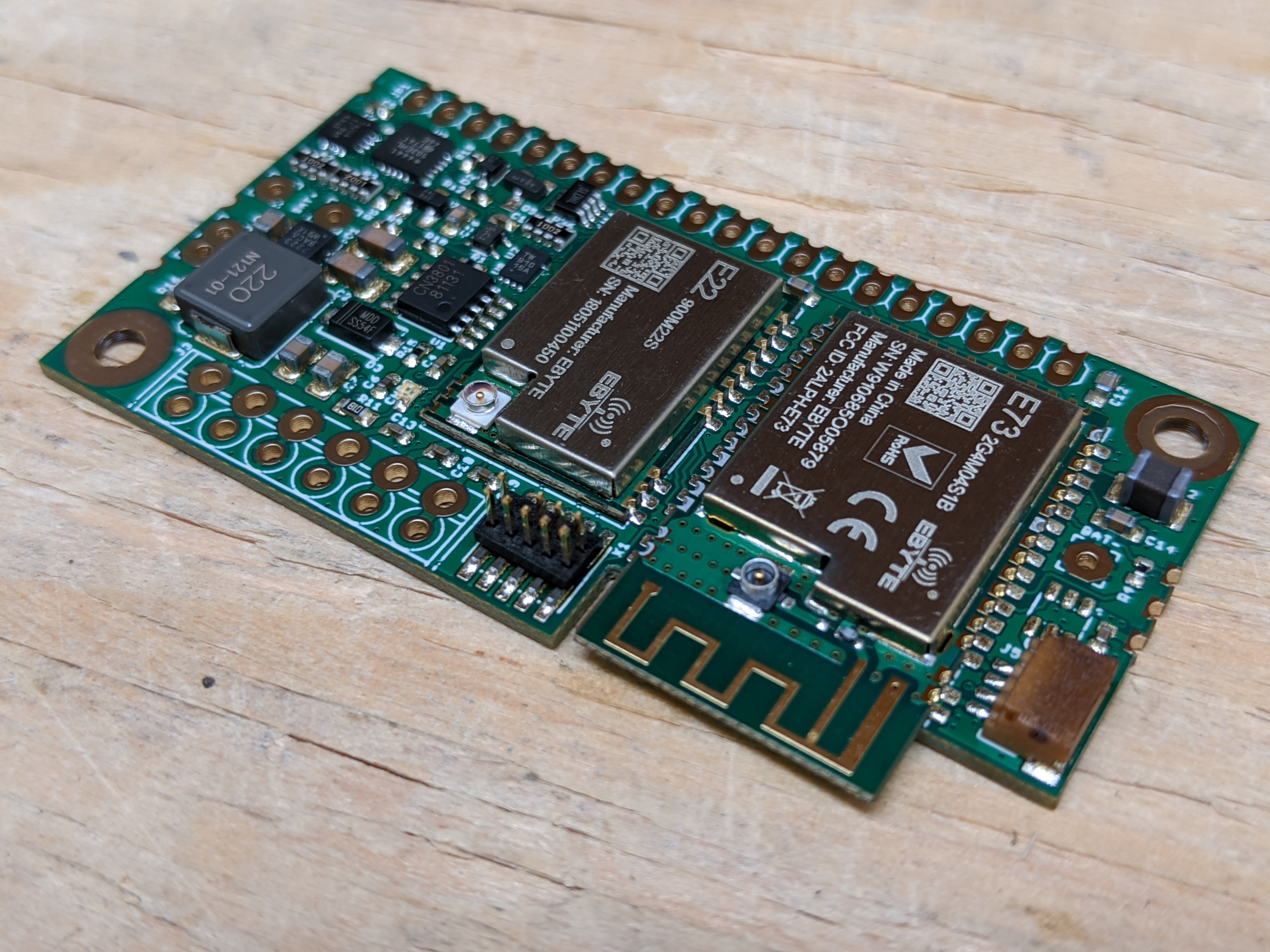
For instance, the design below incorporated a CN3801 based charger, but with a ton of analog circuitry around it involving non-volatile electronic potentiometers and OPAMPs to make the rather limited CN3801 digitally configurable. It's beautiful in a way, but it feels wrong to add so much circuitry just so a low cost charger chip can do what I want it to do. At the same time, it's still limited in output power by using a nonsynchronous rectifier, and it's buck-only so the input voltage needs to be higher than the output voltage. It can be used for LiFePO4 and LTO batteries, but single-cell only, no series packs.
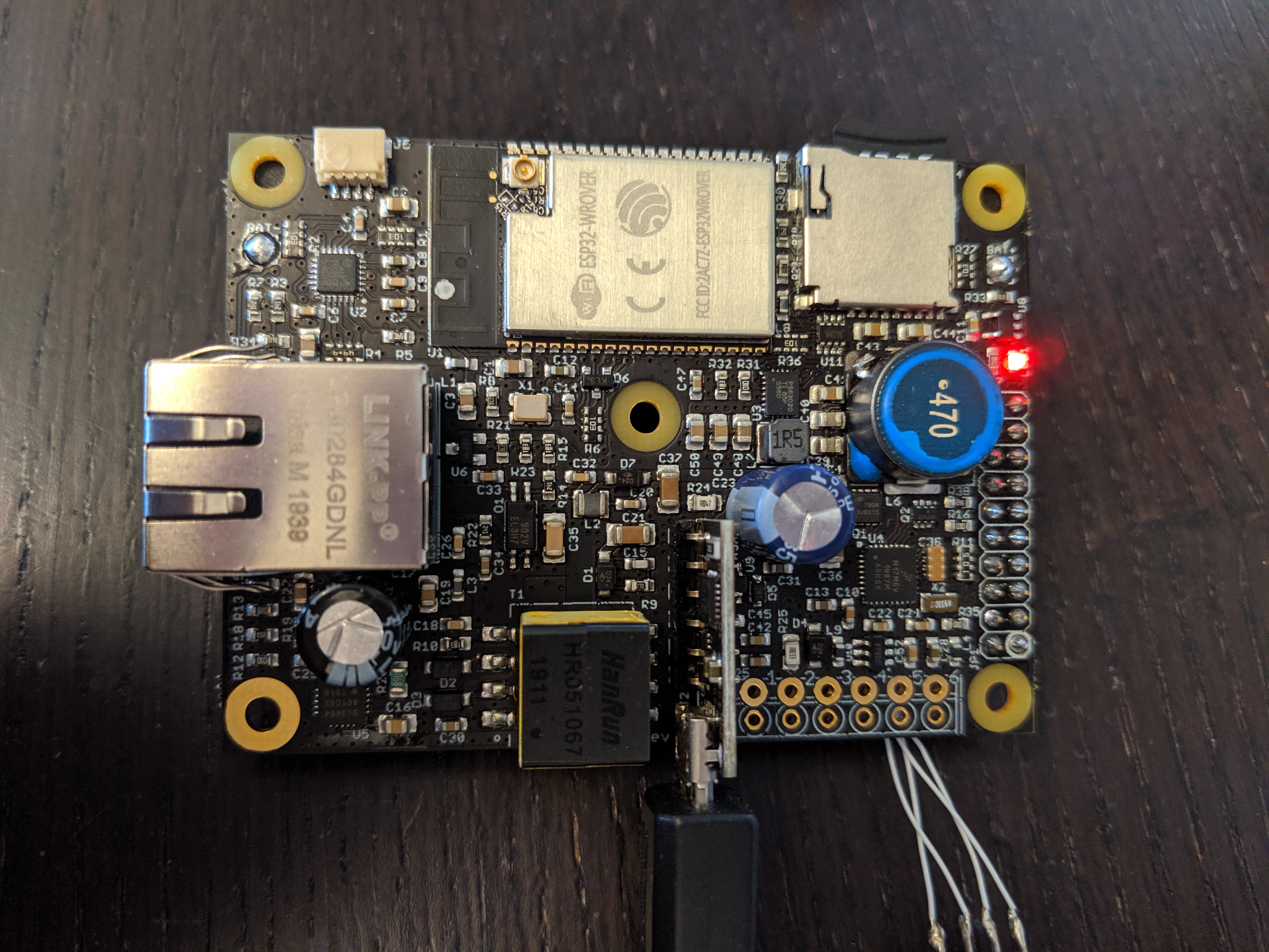
I also did the following board as an early effort to implement microcontroller-based charging, but it had some issues as well, the biggest issue being that it did not respond quickly enough to a sudden increase in input voltage to prevent excessive charge current to the battery, and a corresponding jump in battery voltage. It was built around the fairly expensive MKL17Z32VFM4 microcontroller, which in the mean time also has become unobtainium.
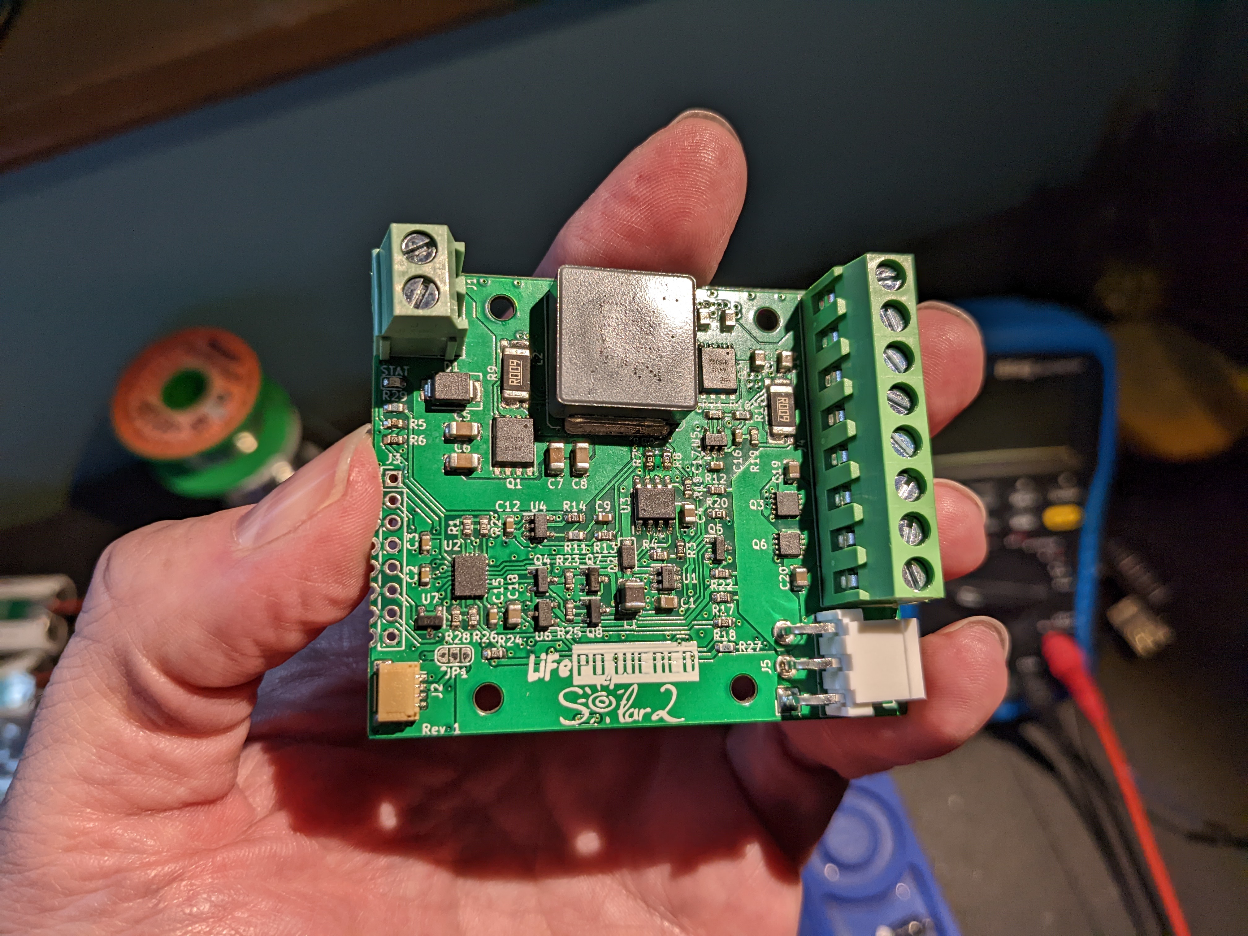
Then I did the board below, optimistically called LiFePO4wered/Solar2, trying to put together a microcontroller based replacement for the LiFePO4wered/Solar1 with some amazing specs such as up to 10 A current, buck/boost for high or low voltage input, single Li-ion cell of any chemistry except LTO or multi-cell packs of any chemistry, automatic solar MPPT, I2C programmable, ...
Lofty goals, and still some of my long term goals, but I think maybe I overdid the initial specs a bit, the board is much bigger than the LiFePO4wered/Solar1, probably over-specified for most applications, and I used an underpowered MSP430 microcontroller so I had to add more external circuitry than I like to make up for its deficiencies such as lack of a multiplier. I also rushed the design a bit so I made several mistakes requiring extensive rework of the prototypes, and something went wrong with the design of the gate driver for the synchronous rectifier, making it necessary to consider a redesign of the gate driver and making it non-synchronous for now and not at all capable of reaching the intended currents.
So, back to the drawing board once again.
Ultra-low cost 32-bit micros
At this point of general dissatisfaction, I'm suddenly hearing news of some new and quite capable 32-bit RISC-V micros coming to market, such as the WCH CH32V003, at extremely low cost (<$0.10, less than the MSP430 I was using). As I started to investigate the potential of this, I also decided to cast my net a little wider and discovered that Puya also is bringing a range of 32-bit (in this case Cortex-M0+), ultra low cost micros to market. I focused in particular on the PY32F003.
I spent quite a bit of time looking at the details of both. (Not at all straight-forward as most of the Puya documentation only exists in Chinese!) To be honest, I'm indifferent about the core used in most cases, for my application it's usually the minute details of the chip implementation and peripherals that are much more important. In this case, here are some of the details I was interested in:
- A hardware multiplier is the only thing that made me favor the Cortex-M0+ core of the PY32F003 over the RISC-V of the CH32V003, which doesn't implement the Multiplier extension. To be able to present nice values in sensible units in I2C registers, scaling is usually necessary and a hardware multiplier comes really in handy to do this while maintaining low power consumption.
- Since you don't want your charger to drain lots of battery power when it's not charging, you need useful low power modes. The PY32F003 lists typical stop mode current of 4.5 μA while the CH32V003 lists about 9 μA. There are still important details to figure out about what exactly happens to the current in undervoltage conditions, what wake sources exist in these modes, etc. But the PY32F003 looks more attractive here.
- The power supply voltage range is important, especially on the low end. The PY32F003 has the advantage here as well, having a working supply voltage range of 1.7 V ~ 5.5 V vs 2.8 V ~ 5.5 V for the CH32V003. This means the PY32F003 can work across the voltage range of a single LTO cell, which I find a huge advantage since my products are targeted at IoT use, often outdoors across extreme temperature ranges, and LTO is the most rugged Li-ion chemistry there is for these applications.
- The PY32F003 has two analog comparators built-in while the CH32V003 has one that can be either an OPAMP or comparator. The two comparators of the PY32F003 is an advantage to me that I can use for short circuit / over current protection on both the battery and the load output. It looks like they can trigger interrupts and send break signals to the timers, so the charger PWM can be stopped in hardware without the delay inherent in a software-only response.
- The PY32F003 has a 12-bit ADC while the CH32V003 ADC is 10-bit. Usually you can't really trust the lower 2 bits or so, some averaging can help there. Either way, two extra bits is very useful if you want to measure tiny voltages across a current sense resistor without extra amplification. It remains to be seen if this will work well enough, but I hope to be able to avoid adding external amplifiers. This is an area that requires more testing.
- The PY32F003 is most likely a bit more expensive than the CH32V003 but it is actually available in distribution. I've seen the touted less-than-$0.10 price point for the CH32V003 in news articles, but I have not actually found chips available for sale anywhere at that price. At $0.22 @ 1000 pieces the PY32F003 is still an amazing value for what you get.
PY32F003 design
The PY32F003 seems like the better option for this design so that's the direction I'm going for now. There are still a lot of details to figure out so there's no guarantee this will actually end up working. I'll be doing tests on the device to answer various important questions before I actually commit to a design. As you can see from the background above, I've been making boards too eagerly before fully understanding all the important details. I want to get it right this time.
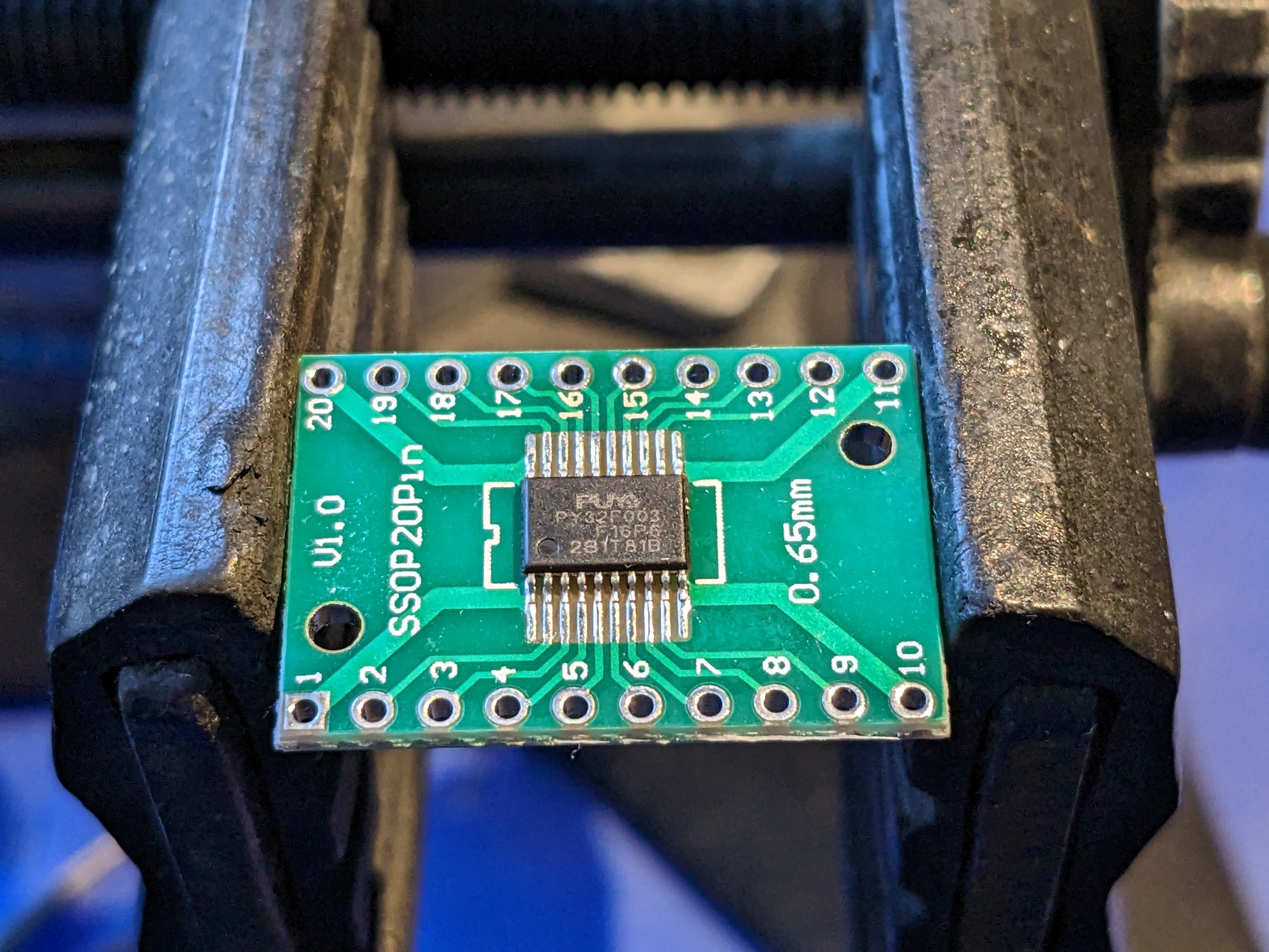
I did a rough high level design and pin assignment for the 20-pin version of the PY32F003 and I think I've figured out a configuration that can do what I need. So, this guy, mounted on a simple breakout will be my test vehicle to answer some important questions.
At this point I'm thinking I want to support two possible topologies.
The first and simplest implementation will be a buck design, the input voltage needs to be higher than the battery voltage. I'm intending to use a DrMOS device as the power switch, so I can get synchronous rectification with automatic DCM mode support, taken care of by the DrMOS device. The input voltage will be referenced against circuit ground, and only single cell Li-ion will be supported.
I want the design to also be able to support an inverting buck-boost topology that will allow the battery voltage to be higher than the input voltage, providing support for higher voltage battery packs with series cells being charged from low voltage solar panels. The downside is that the input voltage will not be referenced to circuit ground, but this is OK in many cases.
The first topology is easy, pretty much any microcontroller timer can produce the single PWM signal necessary. The second topology is more challenging, it depends on being able to configure the PWM peripheral(s) correctly to generate the switch and synchronous rectifier drive signals while being able to support DCM with the addition of an external high-side comparator to turn the synchronous rectifier off when the rectifier current reverses.
I'm intending to experimentally prove both topologies are possible before proceeding with an actual board design.