LiFePO4wered/Solar4 prototype PCB design
The need for a more complete test platform
After having proven that the PY32F003 can provide the needed PWM signals, for the various topologies I might want to support, I wondered what to test next. And I came to the conclusion that maybe I had exhausted what can be learned from the simple chip-on-a-breakout-board setup I have been using. It was time to have an actual power conversion stage connected now.
Breadboarding the power conversion stage presented issues. I considered it briefly but this first implementation was going to use an AOZ5316 DrMOS device, and you can't really get an off-the-shelf breakout board for a package like this:
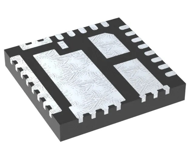
So if I wanted to just do a breakout for this device by itself, I was going to have to lay it out myself. Then there's the issue that the current loops from input cap through power switch, inductor and output caps, and from inductor through output caps and rectifier, have to be compact and have low resistance and inductance for the power stage to work well and not suffer from tons of parasitic switching effects. It really only makes sense to lay them out as a single unit on a board to be representative.
So at that point, the hard part was pretty much done and instead of having a separate power stage PCB and fly wires to other parts like the microcontroller, it seemed easier to just put everything on a single PCB. 🙂
More pin assignment issues
As I dug in more, I found some issues with my existing microcontroller pin assignments. First, I found that the PY32F003 PF2 pin seems to be input only. Unfortunately on this board I need mostly either outputs or analog inputs, and very few digital inputs. I used my JLink debugger to manually try to switch this pin to output in a debug session, and indeed, it did nothing.
I also had some other pin functions duplicated that on closer inspection wouldn't work. For instance, I had planned to use PA5 both to measure the battery pack NTC thermistor and drive the on-board status LED. This seemed like something that could work, if the voltage of the thermistor measurement would never reach the threshold voltage of the LED. Two problems with that though. First, if there is no thermistor connected, the LED to ground made it harder to detect the absence of the thermistor. That could have been worked around, but the second problem was the nail in the coffin for that pin sharing idea: LEDs, when exposed to light, produce a voltage. That would have had the potential to thoroughly ruin my thermistor measurement!
Anyway, trying to shuffle things around, I eventually decided to put the status LED on pin PA13, which also serves as SWDIO for debugging. I will only switch the pin to output after a delay, and have a debugger startup script that will set some flag and check this flag in code before switching pin mode. The status LED will just be disabled while debugging. I had hoped to be able to detect whether a debug session was active some other way, but it seems the Cortex M0+ core does not implement CPU access to the register that can be used for that. Of course, I had to check whether using this pin for debugging while an LED was connected would actually work. I did a test on my simple breakout board and it looks like debugging works just fine with an LED and current limiting resistor connected from SWDIO to GND.
LiFePO4wered/Solar4 rev 1
Once I had decided to make a PCB of the full system, there was no hope for keeping this just a quick and dirty development platform. 🙂 I can't really help myself and had to turn it into a good looking product PCB right away.
Since I'm looking to replace my LiFePO4wered/Solar1 (which has been out of stock due to part shortages), I wanted to make something the same size or smaller. I also wanted to make it more practical by making it compatible with screw terminals, direct wire connection or PCB mounting from the get go. I quickly decided that since the design contains quite a number of passives, I was going to use 0402 size packages for those, instead of the 0603 size I tend to use on larger boards. Of course, some bulk caps and current sense resistors are still going to use larger packages.
To fit it all in a footprint equal to or smaller than the LiFePO4wered/Solar1, while keeping everything on one side to fascilitate PCB mounting, the board has to be dense. So I went with a 4-layer PCB and decided to drop the silk screen part designators, since they'd take up more space than the parts themselves! No great loss there, it will make hand assembly of prototypes just a tad harder but that's about it.
After some pleasant hours spent in KiCad (I find laying out PCBs very relaxing), this is the first prototype of the LiFePO4wered/Solar4:
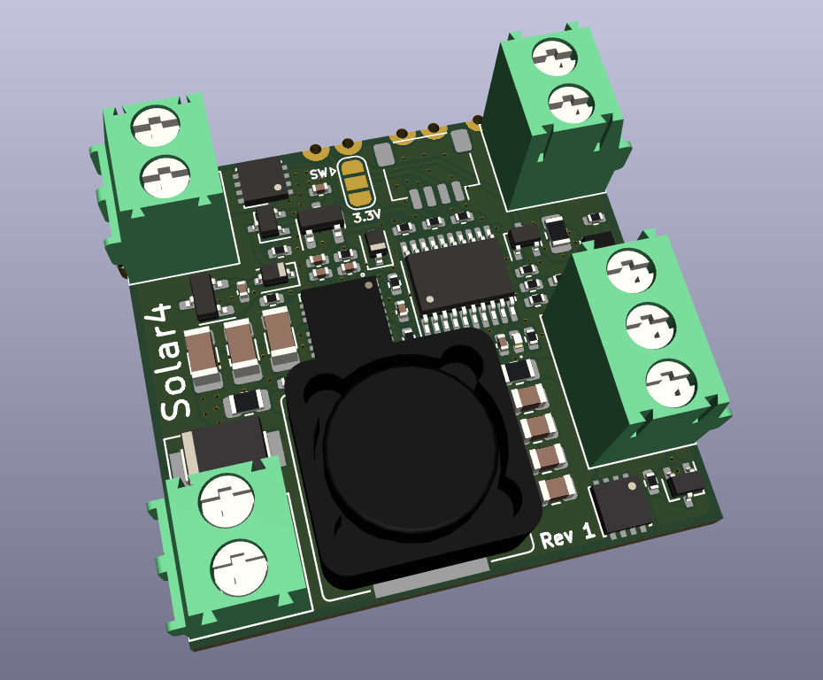
The board is only 33 mm x 31 mm, just a tad smaller than the LiFePO4wered/Solar1 which is 30.5 mm x 35.6 mm. Why LiFePO4wered/Solar4? Well I had already made a LiFePO4wered/Solar2 prototype that didn't work out, so I had to give it a different name so as not to get myself confused. Instead of doing a simple incrementing number, I decided to go for the idea that the system is designed to handle about 4 A input and output current. I know, pretty arbitrary, but, whatever. 🙂
So the plan is to support about 4 A input, charge and output current. MPPT should be automatic, nothing to set up. While the LiFePO4wered/Solar1 had thermal protection and a heater output, the heater needed to be carefully matched to the solar panel, which was inconvenient. In this new design, the heater should automatically use MPPT as well.
Many users should be able to just drop the LiFePO4wered/Solar4 in a design without having to configure anything, but if configuration is required this will be possible over the I2C, using either the castellated pads or the Qwiic connector. I hope to provide some simple tool to do this for users who just want to configure it for their application and not have I2C connected after that.
Anyway, that's all still a ways off as I first need to validate the power conversion stage and write the code to actually make it work. Stay tuned!