Puya PY32F003 undervoltage behavior from STOP1 mode
Next I wanted to see how the PY32F003 would behave when reaching under-voltage condition when in stop mode. According to the specification, the lowest power stop mode current consumption is 4.5 μA typical. At least, that is as long as the chip is within the specified voltage range above the Power On Reset (POR) threshold. Let's check if we indeed can reach this low consumption and what happens when the supply voltage falls below 1.7 V.
There are various levels of stop mode. The specification shows that stop mode with the Main Regulator (MR) on has a typical power consumption of 70 μA. You can switch to the Low Power Regulator (LPR) before activating stop mode to achieve lower consumption. With the LPR active, you can configure it for 1.2 V or 1.0 V output, 1.0 V results in the lowest current draw. I have not yet figured out for what reason you might want to keep it at 1.2 V, so I went for the lowest power stop mode with LPR output at 1.0 V. This seems to be called STOP1 mode in the code, and is the mode that is specified for a typical current of 4.5 μA.
Below is a graph showing current in μA versus supply voltage. The top graph is the full view, while the bottom zooms in on the lowest currents. The voltage was first ramped up from 0 V to 3.8 V and then back down again from 3.8 V to 0 V to see if there would be any difference in behavior going up and ramping down.
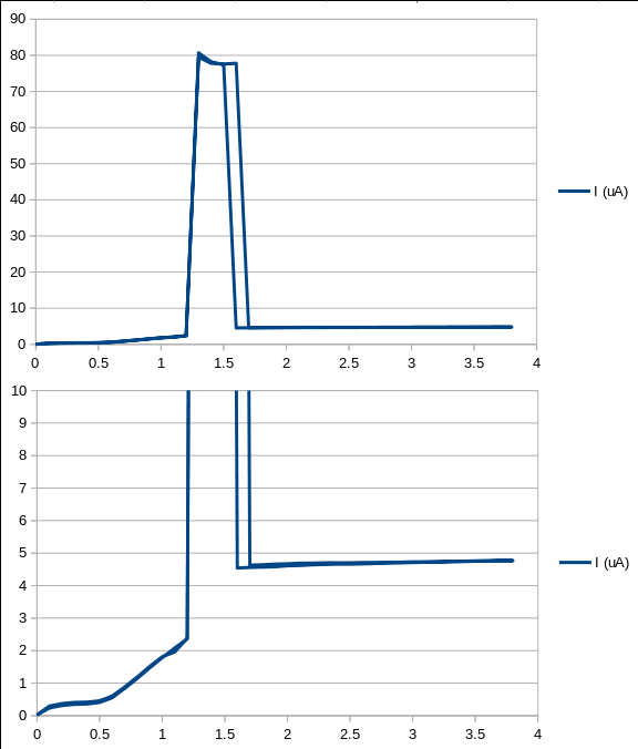
As the graph shows, when the chip is active above 1.7 V, the average current draw is about 4.7 μA, close to the specified typical value. This was at a temperature of 18 °C, since that may affect the stop current, which is something I may test later.
Unfortunately, the chip still shows the higher current draw of about 77 μA between 1.3 V and 1.6 V, as it did when below POR level in run mode. Actually, on the down ramp, the low 4.7 μA current is maintained down to 1.6 V, the current only goes up to 77 μA at 1.5 V.
It seems that once the supply voltage goes below the POR level, the system is switched back to the Main Regulator (MR), which has a typical supply current of 70 μA according to the spec. It is unfortunate that the chip doesn't just keep the last selected regulator active, as this would keep the current low all the way down. But there may be a technical reason for this.
It isn't really a problem I think, even for LTO cells. LTO cells are considered empty around 2.0 V, and LiFePO4 around 3.0 V. As the battery level decreases, a low 4.7 μA can be maintained from 2.0 V down to 1.5 V, giving a 0.5 V margin before this might become a problem. At this point the cell is too deeply discharged and may be damaged.