LiFePO4wered/Solar4 prototype first charge!
"Manual" charging
I finally found some time to work on this project again and was able to get the code to a point where I can control the charging subsystem manually, meaning I have implemented enough code so I can use I2C commands to turn on the charger and manually configure a PWM signal. This is not enough to make a product but it's enough to check whether the charging system hardware actually works and start characterizing it.
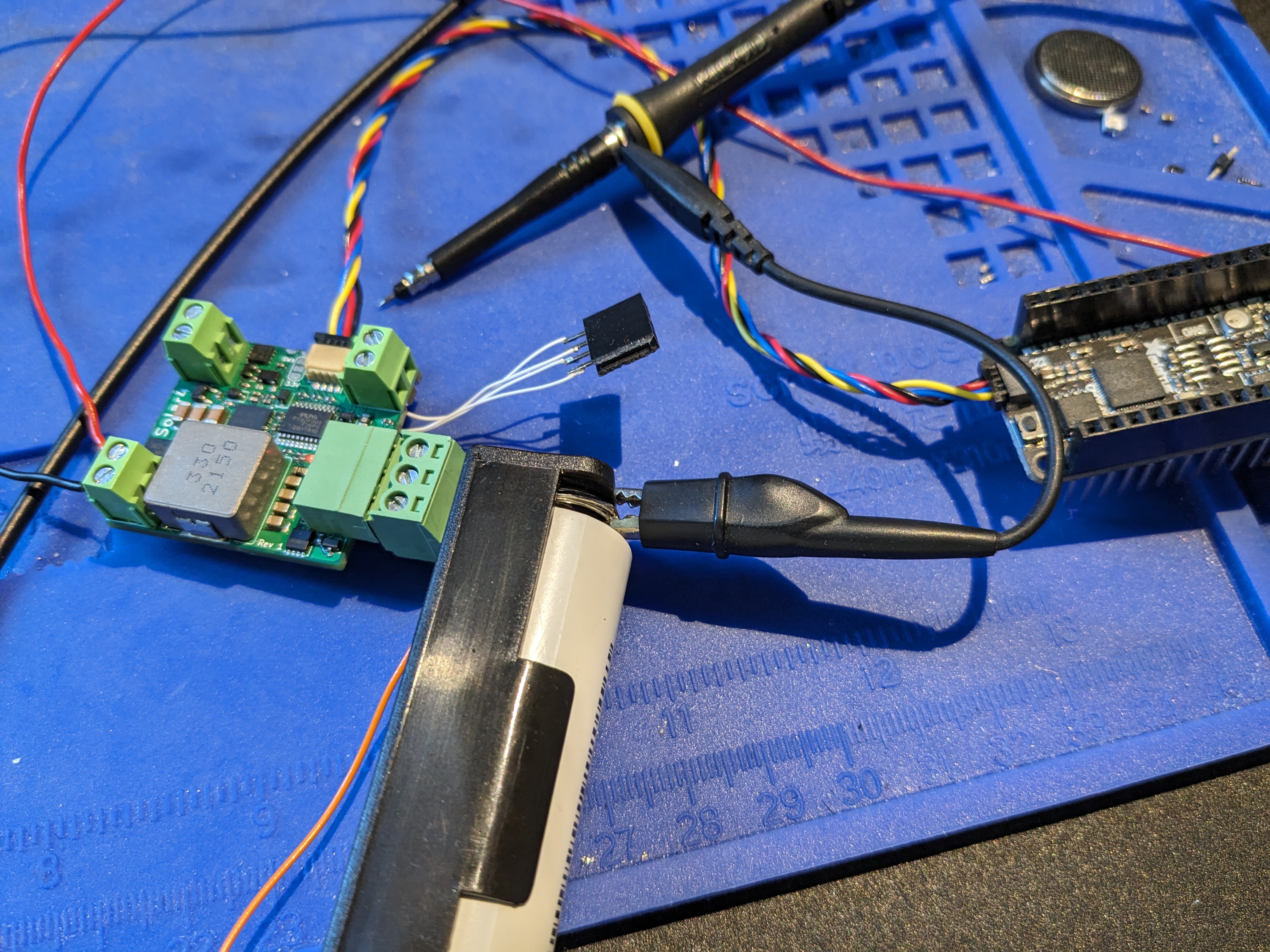
Below is a picture of my test setup. I was using an Adafruit Feather RP2040 running MicroPython to easily read and write I2C registers on the prototype over a Qwiic cable:
PWM signal to DrMOS device
The first thing to check was whether the AOZ5316 DrMOS device actually gets a good PWM signal. This sounds like it should be a no-brainer, but what the DrMOS device wants is actually a bit weird.
Below is a scope trace of the PWM signal coming out of the microcontroller:
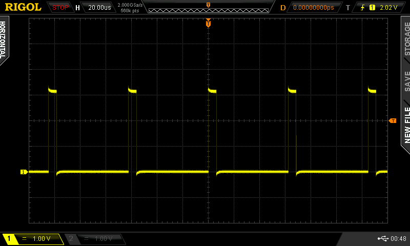
The AOZ5316 has a PWM input that uses three signal levels: high, low and tri-state. If you drive it with a PWM signal that switches between high and low, it will only work in CCM mode. While this may be preferred in general, for a flexible solar charger that may face continuously changing input power, the system should also support DCM mode, which requires the low side switch to do zero-cross-detection with diode emulation.
To make the AOZ5316 behave like this, according to Table 1 on page 9 of the datasheet, you need to switch the PWM input between high and tri-state (with SMOD# pin low), instead of high and low.
To make this happen, I'm driving the PWM input through a diode. This way, the high will drive the PWM pin high while a low from the microcontroller will have the diode block and the AOZ5316 tri-stare voltage clamp will center the PWM pin level within the tri-state region. At least, that was the theory, which still needed to be confirmed. Below is the scope trace of the AOZ5316 PWM pin:
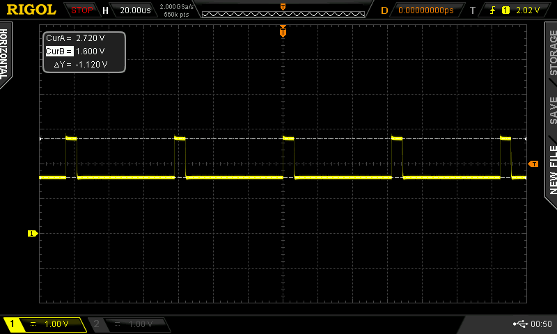
This seems to work as intended, though the high level is marginal according to the datasheet: the logic high just barely reaches the 2.7 V minimum listed. The tri-state level on the other hand is just fine at 1.6 V (valid range is 1.35 V to 1.95 V). I may need to switch this diode to a Schottky type to give that high level a little more margin, especially considering that at low temperatures the diode threshold voltage will increase.
Switching node in DCM and CCM mode
I had a scare at first because even though the PWM input was receiving a valid signal, the AOZ5316 switching node did not show any signal. Turns out the AOZ5316 seems to have some form of latching undervoltage protection, I was enabling the device before the input voltage was present. When I correctly enabled the AOZ5316 after a valid input voltage was present, I was greeted by this scope trace:
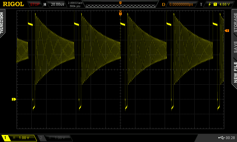
The ringing you see is unfortunate but normal for a buck converter in DCM mode. When the inductor current reaches zero, the inductor will start to oscillate with the parasitic capacitance of the power switches. Below is a zoomed in scope trace:
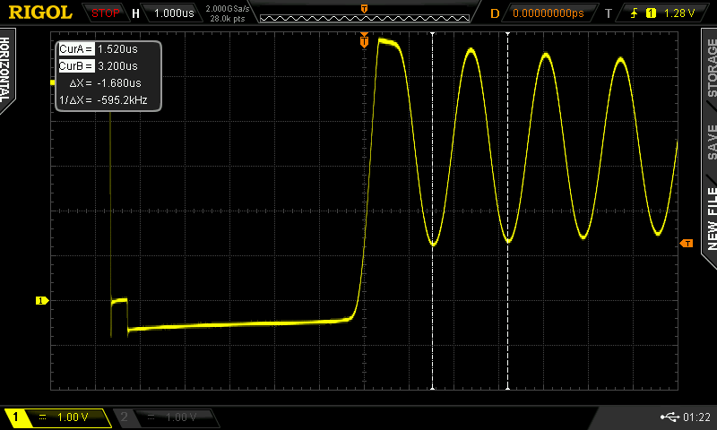
At least the ringing frequency is pretty low (~600 kHz) and sinusoidal so it should not produce any higher harmonics. I don't expect it to be a big issue for EMI.
At this low duty cycle, the converter was only drawing about 20 mA from the input power supply. I ramped up the PWM duty cycle to get the system into CCM mode:
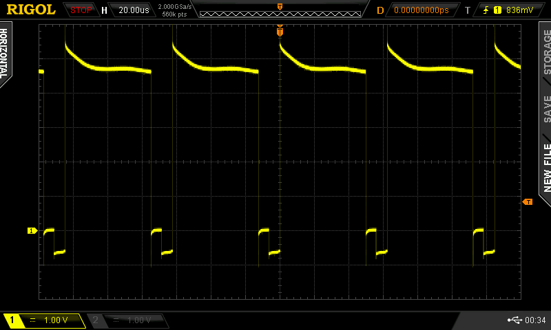
And the current pulled from the input power supply really started to ramp up! I played around a bit and got the input current to go all the way to 2 A (the current limit I had set on my power supply, and more current than I should have been pumping into that single 18650 battery actually 🙂)!
Next steps
Cool, it can charge! Now to give it some brains so it can do it safely by itself. 🙂
The first thing I think I need to do is get a feel for how good my voltage and especially my current measurements are. Because of my current sense resistor values, my decision to not add current sense amplifiers to keep cost and size down, and the way the ADC uses the power supply as reference, I only have a resolution of about 40 mA for current measurements. I'm intending to do some oversampling etc but I still expect the current measurement accuracy to make my life difficult at low currents.
This was expected, and I intend to solve this hardware limitation in software. While at higher currents I intend to use Perturb and Observe or Incremental Conductance MPPT methods, at low currents when the measurements become too coarse for stable control I intend to fall back to Fractional Open Circuit Voltage control, which only depends on voltage measurements. Where this hand-off occurs exactly will depend on how good (or bad) I will manage to get my current measurements.